

Water Automation & Controls
Your pumps, on autopilot — protected, whoever is watching.
Level, pressure, temperature and time automation on top of industrial-grade motor protection, driven through the starter that suits the machine — DOL, star–delta or a VFD. All of it decided inside the controller on your wall, so none of it needs the internet to work.
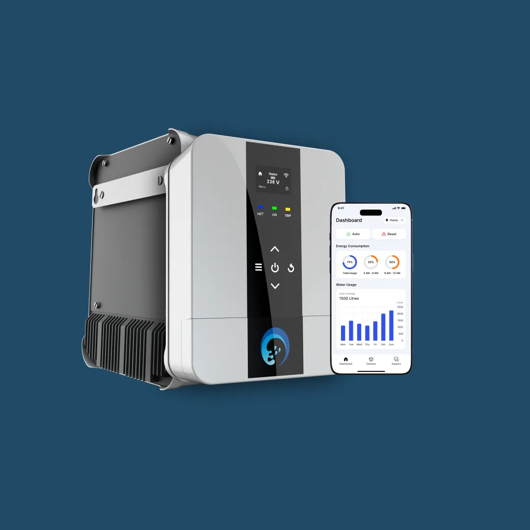
How a pump room stacks up
Four layers, one box
Every system on this page is the same four layers in a different order of importance. The bottom three are what you buy; the fourth is what you turn on when you want to see it from somewhere else.
Control
What switches the motor
DOL, star–delta or a VFD — the power side that actually makes the motor turn, sized to the machine and to what the supply allows.
Protection
What keeps it alive
Under load, overload, under and over voltage, dry run, over cycle, over run and single phasing — armed on every pump, always, locally.
Automation
What decides
Level, pressure, temperature and time. The rules that mean nobody has to remember to switch anything on — or off.
Monitoring
Optional · the IoT layer
Live readings, alerts, history and remote control on your phone. Everything below it keeps working without it.
The line that matters: layers 1 to 3 live inside the APCON controller on your wall. Cut the internet, unplug the router, lose the cloud — the pump still starts on the right level, still stops on the right level, and is still protected against every fault on this page.
Part one
Automations
Five families of decision, all running on the same controller and the same sensors. Most buildings end up using three or four of them at once — a level automation feeding a pressure set, a hot water loop beside it and a schedule on the garden.
Level automation
Fill when the destination is low and the source has water. Stop when it is full.
Level automation is not a float switch with an app bolted on. The controller holds a live number for every tank it can see — percent, litres and metres — and switches the pump against start and stop levels you choose per tank. Because both ends of the transfer land on the same controller, the rule that prevents the overflow and the rule that prevents the dry run are one rule.
- Start and stop level per tank, with a dead band wide enough that ripples and inflow surges never short-cycle the motor
- Source-and-destination logic: a sump below its reserve level vetoes the pump before the motor ever feels the loss of water
- Fill or drain — the same controller runs a dewatering duty by inverting the rule, so a sump pit empties instead of filling
- Multi-level sequencing: a sump, an overhead tank per wing, a flushing tank and a treated-water tank filled in order by one pump set, skipping whatever is already full
- Any sensor mix — ultrasonic (non-contact), hydrostatic transmitter (contact), float or electrode probes — wired, or over LoRa radio where the cable run to the terrace is the expensive part
- An overflow alarm level above the stop level, so a passing valve or a stuck sensor is reported rather than quietly survived
- Auto, semi-auto and manual modes — and a manual run is still a fully protected run
What you set
- Start level
- Stop level
- Source reserve
- Dead band
- Overflow alarm
- Max run time
HPN pressure systems, with PID control
One pressure on every floor — held by a control loop, not by a pressure switch.
A hydro-pneumatic set carries the whole building’s pressure. Run it on a bare pressure switch and it hunts between cut-in and cut-out, which a shower feels as a wave. The APCON controller closes a PID loop around a 4–20 mA pressure transmitter on the header instead: it corrects for how far pressure is off the setpoint, how long it has been off, and how fast it is moving — then trims pump speed to hold the number you set.
- PID on line pressure — proportional to the error, integral to erase the standing offset a proportional-only loop always leaves, derivative to damp the overshoot
- Setpoint in bar, held from the ground floor to the top floor regardless of how many taps are open
- Cascade staging: the lead pump on a drive holds pressure, and as it runs out of speed the next pump stages in — then drops back out as demand falls
- Stage and de-stage delays plus a minimum run timer, so the set never hunts a motor on and off at the margin
- Sleep / no-flow shutdown — when demand ends the set boosts slightly above setpoint and stops, instead of idling against a closed system
- A diaphragm vessel sized to the set, so small draws are served from stored pressure without starting a motor at all
- Suction interlock: the same sump level the rest of the system already knows vetoes the set before it can run dry
What you set
- Setpoint (bar)
- P · I · D gains
- Min / max Hz
- Stage delay
- Sleep threshold
- Suction reserve
Hot water circulation
Hot at the tap in seconds — without a circulation pump running around the clock.
The usual hot water loop runs its circulation pump continuously: perfect comfort, paid for in standing heat loss and pump hours, all day, every day. A controlled loop watches two things instead — the temperature on the return leg, and a flow sensor in the hot line that sees the instant somebody actually opens a tap — and runs the pump only when one of them asks for it.
- Return-leg temperature band — the pump runs when the loop has cooled below your comfort band and stops once it recovers
- Adaptive, flow-triggered circulation: a draw at any tap starts the loop and it stops shortly after the draw ends
- Schedules layered on top, so the loop is simply off in the hours the building does not want hot water
- The heat source in the same plan — heat pump or geyser setpoints and the loop are one decision, not two machines competing over one vessel
- Anti-cycling on the heat source, and a periodic high-temperature cycle where the storage calls for one
- The circulation pump keeps its own dry-run and overload protection: a circulation pump that loses water is still a burnt motor
What you set
- Loop setpoint
- Comfort band
- Schedule windows
- Storage setpoint
- Flow trigger
- Run / rest limits
Timers & schedules
Irrigation, fountains and filtration that run to a plan the controller keeps — through a power cut.
Irrigation and water features are the two duties everyone means to switch on and forgets to switch off. A mechanical timer helps until the power blips and it loses the day; a phone reminder helps until you travel. A scheduler inside the controller runs the cycle whether or not anyone is home — and knows when there is not enough water to spare for it.
- Per-zone start time, run duration and days of the week, set at the panel or from the app
- Cyclic timers — run for N minutes, rest for M — for fountains, filtration and dosing duties that should not run continuously
- MOV zone control: motorised valves work down the zones while one pump holds the line, so the motor is not started and stopped for every bed
- A real-time clock inside the controller, so the schedule survives an internet outage and rides straight through a power cut
- Reserve-level veto — a cycle that would take the tank below the reserve you set is skipped and reported, never silently run
- Run-now, hold-for-rain and per-zone override, without disturbing the schedule underneath
- Every run logged with its duration, so a missed cycle is visible instead of assumed
What you set
- Start time
- Duration
- Days
- Zones / MOV
- Cyclic on / off
- Reserve level
Multi-pump systems & VFD control
Several machines behaving as one — and a drive that trims instead of switching.
A pump room with more than one pump has two failure modes nobody plans for: the lead machine does all the hours and dies early, and the standby seizes because it never ran. Gridding the drivers fixes both. Duty rotates, a healthy pump takes over from one that faults, starts are staggered so the set never takes its inrush together — and where the duty varies, a drive holds the working point instead of switching around it.
- Duty rotation on run hours or per cycle, so the set wears evenly and the standby is a machine that has actually been run
- Automatic changeover — a pump that trips hands its duty to the next healthy machine, and the fault is reported rather than discovered
- Staggered starts and stage delays: four motors never take their starting current in the same instant
- Alternate, parallel and working-standby configurations on common suction and discharge headers
- VFD control on the lead machine — a soft ramp from zero speed, a soft stop that removes the water hammer, and speed matched to the duty
- The affinity laws do the saving: flow falls in step with speed, but power falls with the cube of it, so a pump held at 80% speed draws roughly half
- Mixed sets are normal — one drive holding pressure with DOL machines staged in behind it
What you set
- Pumps in set
- Rotation rule
- Stage delay
- Min / max Hz
- Ramp times
- Changeover on fault
Part two
Protections
Automation is what makes a pump room convenient. Protection is what makes it survive. Every one of these is armed on every pump, decided inside the controller in milliseconds, and logged with its cause the moment it acts.
UL
Under load
Watches
Running current below the minimum set for this pump
The motor is turning but the pump has nothing to push — it has lost suction, the foot valve is passing, the delivery is shut, the impeller is worn or the coupling has sheared. An unloaded pump is usually a pump about to be a damaged pump: the mechanical seal goes first, in minutes rather than hours.
OL
Overload
Watches
Current above the limit, on a time curve so a healthy start is never a trip
A jammed impeller, a seizing bearing, mechanical binding, a motor asked for more duty than its rating, or the tail end of a lost phase. Winding insulation is a temperature story with no undo — cutting in milliseconds is what keeps a rewind from becoming an annual event.
UV
Under voltage
Watches
Incoming voltage below the safe window, per phase
A motor asked to make the same torque at a lower voltage draws more current and runs hotter for it. Brownouts kill more motors than surges do, and they do it quietly — the pump keeps working right up until the winding gives out.
OV
Over voltage
Watches
Incoming voltage above the safe window, per phase
Insulation stress on the winding and cooked electronics downstream. It arrives when a big load is shed on the street, on a generator changeover, or on a poorly regulated supply — and the damage is cumulative long before anything trips visibly.
Dry run
Power-based · sensorless
Watches
True input power (kW), not current alone
When a pump loses water its current barely moves — the power factor is what collapses, so real input power drops hard and unmistakably. That is exactly why power-based detection trips where a current-only relay dithers. The controller learns the loaded running power at commissioning; below the fraction you set, held for your delay, it cuts. No sensor in the tank: the whole detection happens at the panel.
Dry run
Sensor-based
Watches
The water itself — level sensor, float or electrode probe at the source, or a suction pressure switch
Definitive, and earlier: it stops the pump before it has ever run dry, rather than after the electricals notice something is wrong. On borewells and sumps that empty daily, both methods run together — the sensor as the plan, the power signature as the backstop for the day a probe fouls or a cable is cut.
Over cycle
Starts per hour
Watches
The number of starts in a rolling window
Hunting — a jammed float, a leaking foot or non-return valve, a waterlogged pressure vessel, a dead band set too narrow. Every start is where a motor takes its inrush and its heat, so a pump starting forty times an hour is being destroyed by starting. The trip protects the motor; the alert tells you what is actually broken upstream.
Over run
Maximum run time
Watches
Continuous run time against the longest legitimate cycle for that duty
A tank that never reaches its stop level means a leak, a valve left open, or a level sensor that has stopped reporting. This is the protection that catches the expensive failure — the pump that ran all night into a burst line, or into a tank that was never going to fill.
1Φ prevention
Single phasing, reversal & imbalance
Watches
All three phases — presence, sequence and balance
Lose one phase on a running three-phase motor and the other two carry roughly 1.7 to 2 times their current: the winding cooks in minutes and the motor cannot restart on its own. The controller also watches phase sequence — a submersible running backwards delivers almost nothing while looking perfectly healthy — and phase imbalance, which quietly overheats one winding at a time.
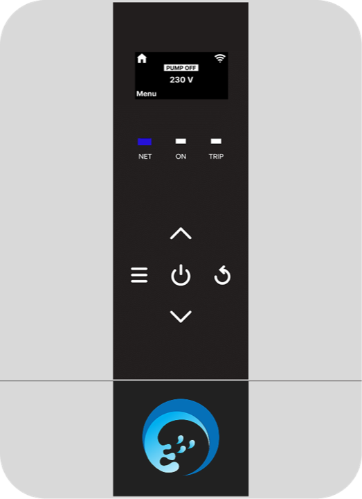
What happens after a trip
A protection that only cuts power is half a protection. The controller also has to decide whether the fault was a passing supply dip or a real failure — and it has to say which one it thought it was.
- Automatic retry after a set delay, with a retry count you choose
- Lockout after repeated retries, so a real fault is never hidden by a hopeful restart
- Voltage faults restore themselves as soon as the supply is back inside the window
- Every trip logged with its cause and a time stamp — on the panel, and in the app
- The TRIP lamp and the display name the fault at the panel, with no phone needed
- Reset at the keypad or remotely, once you know what actually happened
Part three
Controls
Under every automation there is a starter making the motor turn. Which one you need is decided by the motor’s size, the load it starts against and what your supply authority allows — not by a feature list. The curve under each diagram is the whole argument.
DOL — Direct On Line
Full voltage, straight to the motor.
One contactor closes and the motor sees the full supply from standstill. It is the simplest, cheapest and most robust way to start a pump, with the fewest parts that can fail — and it is the right answer for the great majority of transfer, level and circulation duties, where a short inrush on a small motor bothers nobody.
- Starting current
- 6–8 × full load
- Starting torque
- 100%
- Typical range
- Up to ~7.5 kW / 10 HP
- Speed control
- None — one speed
Best for: Level and transfer pumps, boosters, circulation duties, and anything the supply authority allows to start direct.
Star–Delta
Start in star to get moving, change to delta to run.
In star, each winding sees about 58% of line voltage, which draws roughly a third of the DOL inrush — and delivers roughly a third of the torque. Once the motor is near speed the controller changes it over to delta for full voltage and full torque. It needs a motor with six leads and windings rated for delta running, and the changeover timing has to suit the load: too early and the delta step is nearly a DOL start, too late and the motor has been loafing in star.
- Starting current
- ≈ 2–3 × full load
- Starting torque
- ≈ 33%
- Typical range
- ~10–50 HP
- Speed control
- None — two steps
Best for: Larger motors on light starting loads, and sites where the DISCOM caps direct-on-line starting above a rated size.
VFD — Variable Frequency Drive
Rectify the supply, then rebuild it at the frequency the duty needs.
The drive turns the incoming AC into DC, then synthesises a new three-phase waveform at whatever frequency it chooses. Because it starts the motor at near-zero frequency, starting current never has to exceed full load current — and because it can hold any speed in between, it is what makes a PID pressure loop possible at all. It also removes the water hammer at stop, which on long risers is worth as much as the energy.
- Starting current
- ≤ 1 × full load
- Starting torque
- Full, from zero speed
- Typical range
- 0.75 kW upwards
- Speed control
- Continuous, 0–50 Hz
Best for: Pressure systems, variable demand, long or hammer-prone lines, and any duty that spends most of its life at part load.
Multi-pump grid
Several starters, one set
A real pump room rarely picks one of the three. The usual answer is a drive on the lead machine trimming the last few percent, with DOL or star–delta pumps staged in behind it — all of them gridded on one control bus, deciding against the same level and pressure readings.
- Two to eight pumps behaving as one system, on common suction and discharge headers
- Mixed starter types in one grid — a drive on the lead machine, DOL or star–delta on the machines staged in behind it
- One shared signal set: the level, pressure and flow readings every driver in the grid decides against
- Duty rotation across the grid on run hours, so no machine carries the whole set
- Automatic changeover to the next healthy pump when one trips, with the fault raised rather than absorbed
- Staggered start delays so the set never takes its combined inrush in a single instant
- Every protection on this page armed independently for every pump in the grid
The starter you already have comes out
The APCON smart driver is not something added next to your panel — it takes that panel’s place on the wall. Starter, controller, protection and monitoring in one box, on the pumps, tanks, plumbing and wiring you already own. A single-pump retrofit is a few hours; a full pump room is usually a day or two.
- No replacement pumps
- No civil work
- Any pump make or age
- Existing wiring stays
- 1Φ and 3Φ
- Running in hours, not weeks
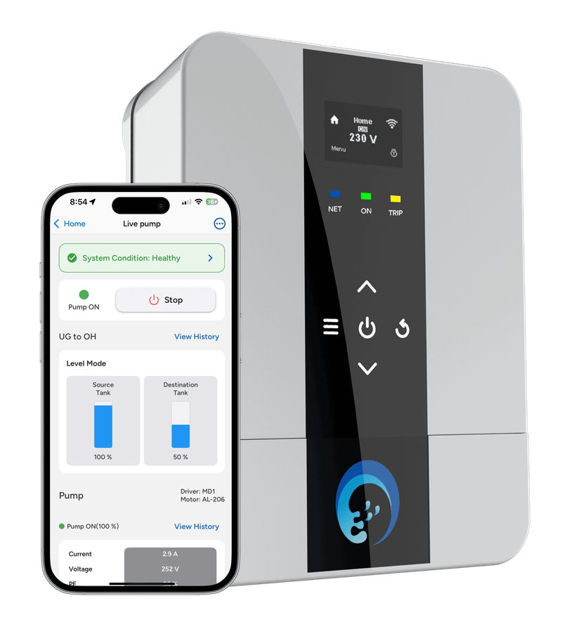
Part four · optional
Monitoring
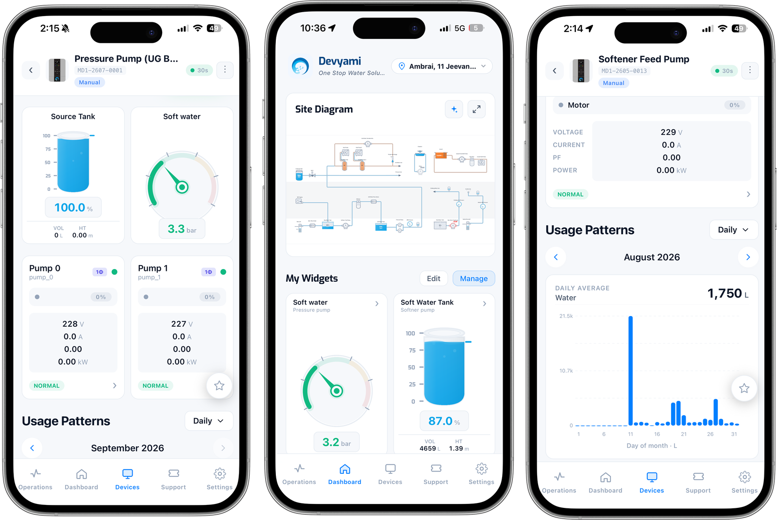
Every controller on this page can talk to the Devyami platform over Wi-Fi. Turning that on does not change how your water system behaves — it changes how much of it you can see, and how early you hear about a problem.
Live, from the panel to your phone
- Pump state — running, stopped, tripped — with the reason attached
- Current, voltage and true input power, per phase, while the motor works
- Tank levels in percent, litres and metres, every tank on the controller
- Line pressure in bar, loop temperature in °C, flow in LPM with a running totaliser
- Run hours and start counts per pump, the two numbers that predict a failure
Told, not discovered
- Push alerts the moment a protection trips — with which protection and when
- Overflow, low-level and night-flow (leak signature) alerts
- Device offline and power-failure notifications for the site
- A time-stamped event log of every switch, trip, changeover and setpoint change
- Exportable history for audits, billing disputes and consumption planning
Changed, from anywhere
- Start / stop and auto / manual from the app, on any pump
- Setpoints and schedules edited remotely — levels, pressure, timers, bands
- Multi-site dashboards with roles for owners, managers and operators
- Our support team reading the same live data, so most faults are diagnosed without a site visit
- Over-the-air firmware updates, so a controller improves after it is installed
Where the line is drawn
An add-on, never a dependency
Monitoring sits on top of the automation and the protection — it never sits inside them. Switching levels, pressure setpoints, schedules and every protection live in the controller’s own memory and run on its own processor. A site with the router unplugged for a month automates and protects exactly as it did on day one; when the link comes back, the totalisers and the event log sync up and nothing is missing from the record.
What monitoring adds is diagnosis. A current trend that is creeping up, a pressure trend that sags a little more each week, a night-time flow that should not exist — those are failures announcing themselves weeks early, and they are invisible to a system that only switches.
Live demo, app screens, water metering and multi-site dashboards live on that page — this one stays on the controls.
Automation & controls, answered
What is water automation, and what does a water controller actually do? +
Water automation is the layer that decides when a pump should run and stops it when it should not. An APCON controller reads the tank levels, line pressure, temperature or the clock, applies the rules you set — start level, stop level, pressure setpoint, schedule — and switches the motor through its own starter. Underneath that it protects the motor electrically against dry run, overload, voltage faults and single phasing. Everything in that loop runs inside the controller on your wall, not in the cloud.
Does pump automation and protection keep working without internet? +
Yes, completely. Level switching, pressure control, schedules and every protection run locally inside the controller. The internet only carries the view, the alerts and remote setpoint changes to your phone — it is never part of the decision to start a pump or to cut power to a motor in trouble. A site with the router unplugged still automates and still protects.
DOL, star–delta or VFD — which starter do I need? +
DOL for most pumps up to about 7.5 kW (10 HP): simplest, cheapest, and a short inrush on a small motor bothers nobody. Star–delta for larger motors on light starting loads, or where the electricity supplier caps direct-on-line starting above a rated size — it starts at roughly a third of the DOL current and a third of the torque, then changes over to delta to run. A VFD where the duty varies: it starts within full load current, holds any speed in between, makes PID pressure control possible, and removes the water hammer at stop. In a multi-pump set the three are often mixed — a drive on the lead machine with DOL pumps staged in behind it.
What is the difference between power-based and sensor-based dry run protection? +
Sensor-based dry run watches the water: a level sensor, float or electrode probe at the source, or a pressure switch on the suction line. It is definitive and it acts before the pump has ever run dry. Power-based dry run watches the motor instead — when a pump loses water its current barely changes but the power factor collapses, so true input power drops sharply. That needs no sensor in the tank at all. On borewells and sumps that empty daily we normally run both: the sensor as the plan, the power signature as the backstop for the day a probe fouls or a cable is cut.
Why does over-cycle protection matter if the pump is switching correctly? +
Because every start is where a motor takes its inrush and its heat. A pump that starts forty times an hour is being destroyed by starting, and the cycling itself is a symptom — a jammed float, a leaking foot or non-return valve, a waterlogged pressure vessel, or a dead band set too narrow. Over-cycle protection cuts the motor to save it, and the alert points you at the fault that is causing the hunting.
Can one controller run several tanks or several pumps? +
Yes. A single APCON smart driver reads the source and destination tanks of a transfer and switches the pump between them. A multi-level controller reads several tanks sharing one pump set and sequences the pump between them, skipping whatever is already full. For pumps, a multi-pump grid runs two to eight machines as one system with duty rotation, staged starts and automatic changeover — with every protection armed independently on each machine.
Do I have to replace my pumps or my panel to automate them? +
No. The APCON smart driver takes your existing starter panel’s place on the wall — it is the starter, the controller and the monitoring in one box — and your pumps, tanks, plumbing and wiring stay exactly as they are. A single-pump retrofit is typically a few hours and a full pump room a day or two, with no civil work and no replacement pumps.
Is the IoT monitoring compulsory? +
No. Automation and protection are the product; monitoring is a layer on top of them. A controller with the Wi-Fi never configured still switches, sequences and protects exactly the same. What you lose without it is visibility — live readings, push alerts the moment a protection trips, the event log, remote setpoint changes and multi-site dashboards. Most sites turn it on because the diagnosis it enables is worth more than the convenience.
Tell us what your pump room looks like today
Send us the pumps, the tanks and the panel you already have — we design the automation, pick the starters, set the protections and hand it over commissioned.