

HPN & Multi-Pump Pressure Systems
Constant pressure on every floor — and the line pressure to prove it.
Gravity from a terrace tank gives the top floor a dribble and the ground floor a fire hose. A hydro-pneumatic set fixes that by holding one pressure across the whole building — but a pressure set that nobody monitors is a black box with three motors in it. Metering the line pressure is what turns it into a system you can actually run.
Hydro-pneumatic system · booster pump automation · constant pressure · line pressure monitoring · BMS

Step 1 of 7
The system
Water arrives in the sump under the ground. A booster set — three pumps in parallel on shared headers — sends it straight up the building to every floor. There is no tank on the roof: the set holds the pressure.
Read the tour as text
- 1. The system. Water arrives in the sump under the ground. A booster set — three pumps in parallel on shared headers — sends it straight up the building to every floor. There is no tank on the roof: the set holds the pressure.
- 2. One pressure reading runs the set. A pressure transmitter on the line leaving the pump room reads the pressure in bar, continuously, and sends it to the panel; the dial gauge beside it shows the same pressure on site. Everything the set does is judged against this one number — here, a setpoint of 3.5 bar.
- 3. The pressure vessel. A diaphragm vessel on the header holds water under pressure. A small draw — one tap at night — is served from it, and no pump starts for it.
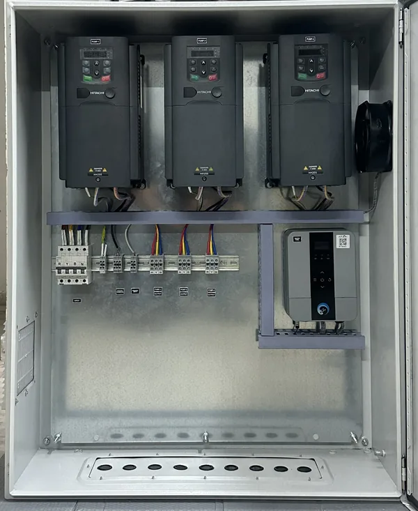
- 4. One panel on the wall. The APCON Multi Pump Controller and a drive for each pump are inside one closed panel. Every cable enters from the bottom: the supply, the sump level, the pressure signal, and one cable out to each pump.
- 5. Taps open — the controller picks a pump. Taps open on three floors and the pressure dips. The controller starts the pump with the fewest starts — P2 and P3 are level on 40, so the one with less run time, P2. Its drive speeds up just enough to bring the line back to 3.5 bar, and holds it there.
- 6. Peak demand — a second pump stages in. Every floor is drawing now. P2 reaches full speed, and when that is not enough the next pump by the same rule — P3, with fewer starts than P1 — stages in after its delay. The two share the load and the pressure holds.
- 7. Demand falls — the set steps down. As the taps close P3 drops out and P2 slows; once the flow stops it stops too, and the vessel holds the line. Every start is counted, so whenever the pressure dips again the controller picks the pump with the fewest starts, then the least run time — and all three wear evenly. Every start is logged in the app.
The working drawing
How it works, on one drawing
The same system as a live schematic — every pipe, pump and signal, and what the controller is doing right now.
What makes it work
The parts of the diagram above that are doing the real work.
PID control, not on/off
A pressure transmitter on the header feeds a PID loop that holds your setpoint continuously — correcting for how far off it is, how long it has been off, and how fast it is moving. That is what a shower feels as steady pressure instead of a pump hunting between a cut-in and a cut-out.
VFD: speed instead of switching
The drive trims pump speed to match demand rather than slamming a motor on and off. Softer starts, less wear, and no pressure spike at every changeover. Output frequency, drive faults and running hours are all readable in the app alongside everything else.
Pumps in parallel, as equals
Two or more pumps share common suction and discharge headers. As demand rises the next pump cascades in; as it falls, that pump drops back out. There is no fixed lead or standby: each start goes to the pump with the fewest starts, then the least run time, so the set wears evenly — and a pump that faults is passed over for the next healthy one.
The control logic
One pressure on every floor — held by a control loop, not by a pressure switch.
- PID on line pressure from a 4–20 mA or 0.5–4.5 V transmitter — proportional to the error, integral to erase the standing offset, derivative to damp the overshoot
- Proportional or time-delay control where a full PID loop is more than the duty needs
- Cascade staging: the running pump's drive holds pressure, and as it runs out of speed the next pump stages in — then drops back out as demand falls
- No fixed lead or standby: each start goes to the pump with the fewest starts, and between equals the one with the least run time
- A staging delay and a maximum-working-pumps limit, so the set never hunts a motor on and off at the margin
- Flow-based stop, so the set does not idle against a closed system once demand ends
- A diaphragm vessel sized to the set, so small draws are served from stored pressure without starting a motor
- Suction interlock: the sump level the rest of the system already knows vetoes the set before it can run dry
What you set
- Setpoint (bar)
- P · I · D gains
- Min / max Hz
- Staging delay
- Max working pumps
- Suction reserve
How it is done
Every step below is a retrofit on the system you already have — no replacement pumps, no civil work.
- 1
Meter the header
A pressure transmitter on the system line reports live pressure in bar, continuously. That single reading is what the whole set is judged by, and it is the first thing the app shows you.
- 2
Cascade on demand
As demand rises and pressure sags, the next pump cuts in; as demand falls, it drops back out. The building sees one steady pressure instead of a pump hunting between extremes.
- 3
Fewest starts first
No pump is the fixed lead or the standby — they are equals. Each time the line needs another pump, the controller starts the one with the fewest starts, and between equals the one with the least run time. Every machine wears evenly and none stands idle long enough to seize, and a pump that faults is passed over for the next.
- 4
Watch the trend, not just the number
The app plots line pressure through the day and logs every changeover, so a set that is starting to struggle shows up as a trend long before it becomes a complaint from the top floor.
What it takes
- Pressure transmitter on the system header for live line pressure
- Two or more pumps, each on an APCON smart driver
- Pressure vessel sized to the set
- The Devyami app for live pressure, each pump's starts and run hours, and changeover history
What you get
- Constant pressure from the ground floor to the top floor
- Live line pressure in bar, with a trend through the day
- Even wear across the set — starts and run time balanced automatically
- Every cascade and changeover logged — BMS-grade visibility for the pump room
Controllers that do this
Engineered and built by us — each one the starter, the controller and the protection in a single box.
Multi Pump Controller
Up to six pumps — drives and direct-on-line — running as one system.
View product →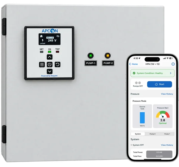
Twin Motor Driver
Two pumps from one controller — duty shared, each motor protected on its own.
View product →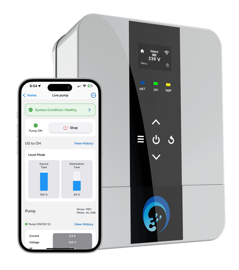
Motor Driver
Starter, controller and motor protection for one pump — single or three phase.
View product →Questions, answered
Why monitor line pressure if the system already controls it? +
Because control tells you what the set intended and monitoring tells you what the building got. A pressure trend that sags a little more each week is a set losing capacity — a failing pump, a waterlogged vessel, a clogging line — and it is visible weeks before anyone on the top floor complains.
Which pump starts first — and does it matter? +
It matters. With a fixed lead, that one pump does all the work and fails years before the others, which meanwhile seize from never running. So there is no fixed lead or standby: each time the line needs a pump, the controller starts the one with the fewest starts, and between equals the one with the least run time. Starts and hours stay level across the set, and every pump is proven to work on the day it is needed.
More water automation
Every automation runs on the same APCON controllers — and keeps working without the internet.
Tank automation — single & multi-tank
Two ways to read a tank — non-contact ultrasonic on the lid, or a contact hydrostatic level transmitter hanging in the water. Both report live percent and litres, warn you before an overflow or an empty tank, and feed the same reading the controller switches your pumps on.
How it is done →Hot water circulation & heat pump control
A monitored circulation loop keeps hot water at every tap the moment it opens — no running the shower cold for a minute. The app watches loop temperature, runs the circulation pump only when needed, and coordinates heat pumps and geysers so comfort never fights efficiency.
How it is done →RO controller
The RO plant’s own numbers on your phone: raw, treated and reject TDS, pH and ORP, flows, the pressures either side of the membrane, and every pump, switch and tank float — with an alert the moment something trips.
How it is done →Water batching control
Digital flow meters turn every pipeline into a number you can manage: litres pumped today, consumption per wing or per site, and totals you can export. Water metering is also your leak detector — flow at 3 AM when everyone is asleep is a leak announcing itself.
How it is done →Timers & schedulers
Garden irrigation, landscape zones and fountains run to a schedule you set once from your phone: start time, run duration, which days, which zone. The controller keeps time locally, skips a cycle when the tank is too low to spare the water, and logs every run.
How it is done →Multi-pump controls
Run two to six pumps as one set of equals: each start goes to the pump with the fewest starts so they wear evenly, extra pumps stage in when demand rises, and the next pump takes over the moment one trips.
How it is done →Pump controls — DOL, star–delta & VFD
DOL, star–delta or a variable frequency drive: how each one starts a pump motor, the starting current it draws, and which one your pump needs — with automation and protection on top of every one.
How it is done →Motor protection
Dry run (with and without a sensor), overload, under load, under and over voltage, phase loss, over-cycling and over-run — nine protections armed on every APCON controller, logged with their cause.
How it is done →More in Smart Water IoT App
Want HPN & multi-pump pressure systems on your site?
Tell us what your pump room looks like today — we design, retrofit and stand behind the whole system.